top of page

SAUNO LLC.
Production, sale and service of impact-etching, laser engraving, milling
and grinding machines since 1997.
New control motherboard
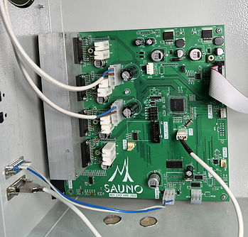
- Multilayer board with improved protection against electrical interference for use in stone processing workshops.
- Modern motor control chips provide more precise and smooth motion control.
- Control of additional Y1 drive for machines with dual Y-axis drive.
- No onboard cooling fan required.
- There are no stepper motor cables or R sensor wires. Fewer wires and connections – higher reliability.
Higher movement accuracy and engraving quality

- The engraving pitch can be adjusted more precisely.
In version 11, the pitch changed at intervals of 0.25 mm. In version 12.1, the pitch change interval is 0.00625 mm.
- The accuracy of the leve trackingl of the workpiece surface during the engraving process is also doubled, which ensures smooth operation and improves the quality of engraving.
Additional raster methods

In the Material panel, in addition to the three existing ones, two new methods for converting an image to a raster have appeared:
– P4 (raster template),
– P5 (modified raster template).
Examples of images converted to raster are shown in Fig. 1.
The dimensions of the raster element can be adjusted using the “M” parameter, as shown in Fig. 2.
Click on the photo on the left to enlarge.
Entering the workpiece shape from the machine console into the Engrave program

The contour of a workpiece of complex shape, for example the one in Fig. 1, can now be specified in the Engrave program using the machine.
- On the machine control panel in manual mode, the needle is brought to the next point on the edge of the workpiece.
- By pressing a button on the remote control, the point is transferred to the Engrave program. Point by point, the outline of the workpiece appears on the computer screen, as shown in Fig. 2.
- The entered contour is used in the workpiece viewing mode, see Fig. 3.
It is easy to fit images for engraving into an irregularly shaped workpiece and adjust their sizes so that when engraving the tool does not go beyond the workpiece.
The exit of the image beyond the workpiece is indicated by red lines.
The acceleration of the tool and the offset of the level sensor tip point below are taken into account, as indicated by the thin yellow line around the portrait in Fig. 3.
Manual control panel in Engrave program

The manual control panel of the Engrave program duplicates the machine control panel.
It can be useful in a situation where you control the machine from a remote computer.
Increased engraving frequency

The maximum beat frequency when engraving images has been increased to 800 Hz in Turbo mode.
Engraving of multi-layer images has been simplified

Repeat layers, an image mask and a workpiece outline can now be added to the engraved image without creating a layout file.
Moreover, layers of repeated passes can be added and removed while engraving.
The photo shows that multiple repeat passes can be added to an engraved landscape, each set to a different impact force.
Traversing a contour with merging layers

In previous versions, traversing along a contour could only be done on the current layer.
In version 12.1, the traversal path is created over several layers.
Can be used optionally:
- visible layers,
- selected layers,
- all layers of the layout.
bottom of page